“Mesla” – an electric trike with two seats – Part 1
August 30, 2023
I’ve been thinking about building an electric trike for some time already, but I never pulled the trigger on buying the motor and other components as I couldn’t find a reasonable battery pack which didn’t cost an arm and a leg. Also, as the trike is meant for the kids, it would need to be easy enough to control that a kid can drive it. Most electric motors I had in mind are not so great for low RPM uses without a gearbox, and that would add more cost and complexity.
I decided that I’m going to find a cheap mobility scooter! It’s slow (20km/h), rugged, and has all the steering components and electronics already in place. As a plus it’s made for elderly or disabled adults, so it’s easy to control and can also carry heavier load so even I could drive it.
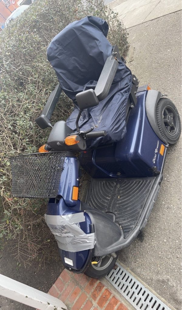
After following the local second-hand website for few months, I finally found something that seemed to be a good fit for my needs. It was pretty banged up on the outside, but it was solid otherwise and even came with a fancy charger.
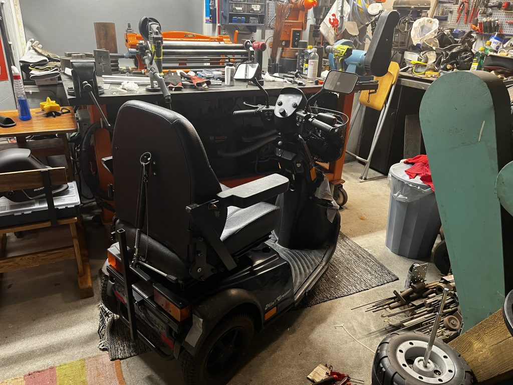
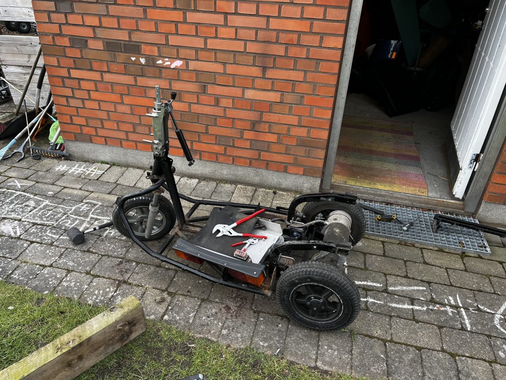
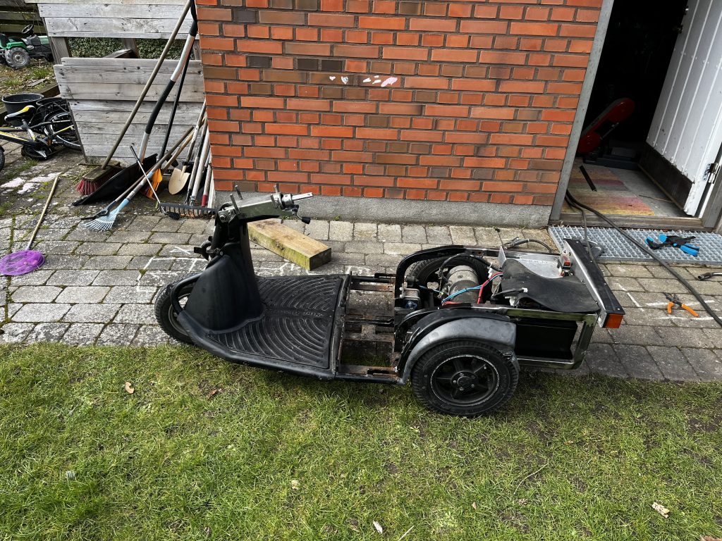
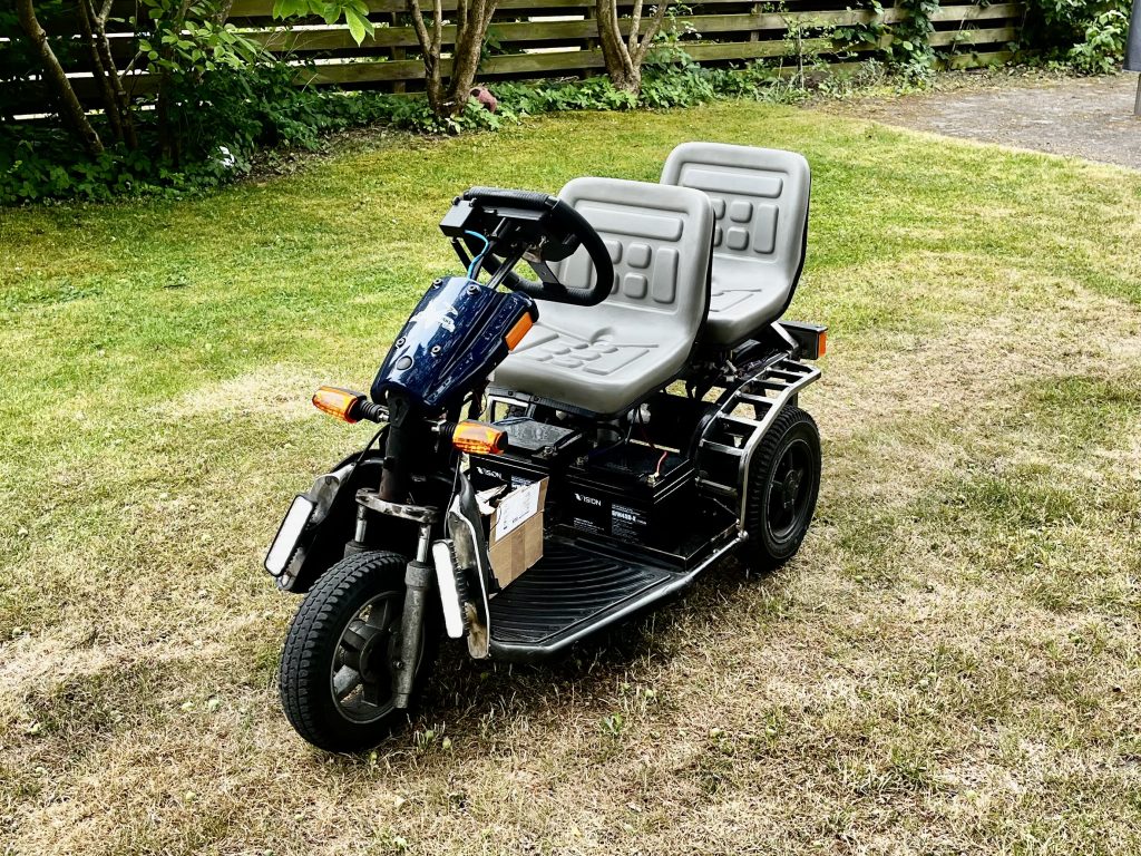
This is how it looks after some work:
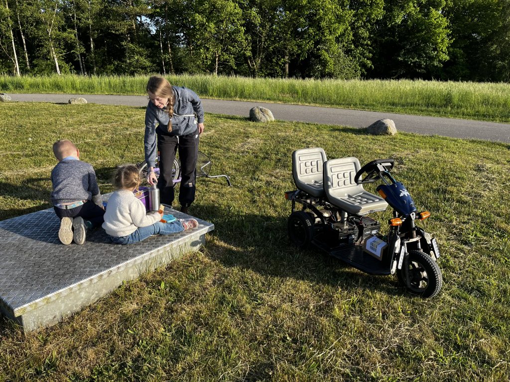
The nearly completed trike. It has all the bells and whistles, and can carry nearly 200kgs!
Build Log:
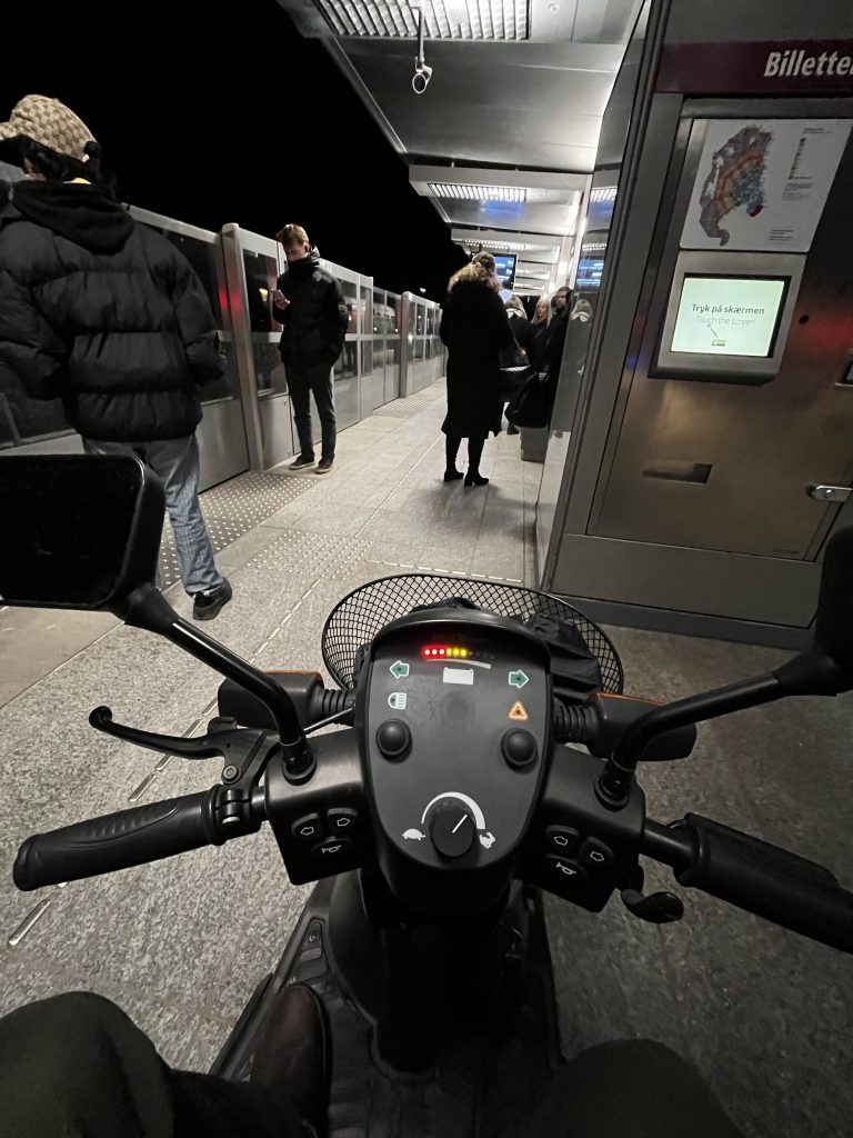
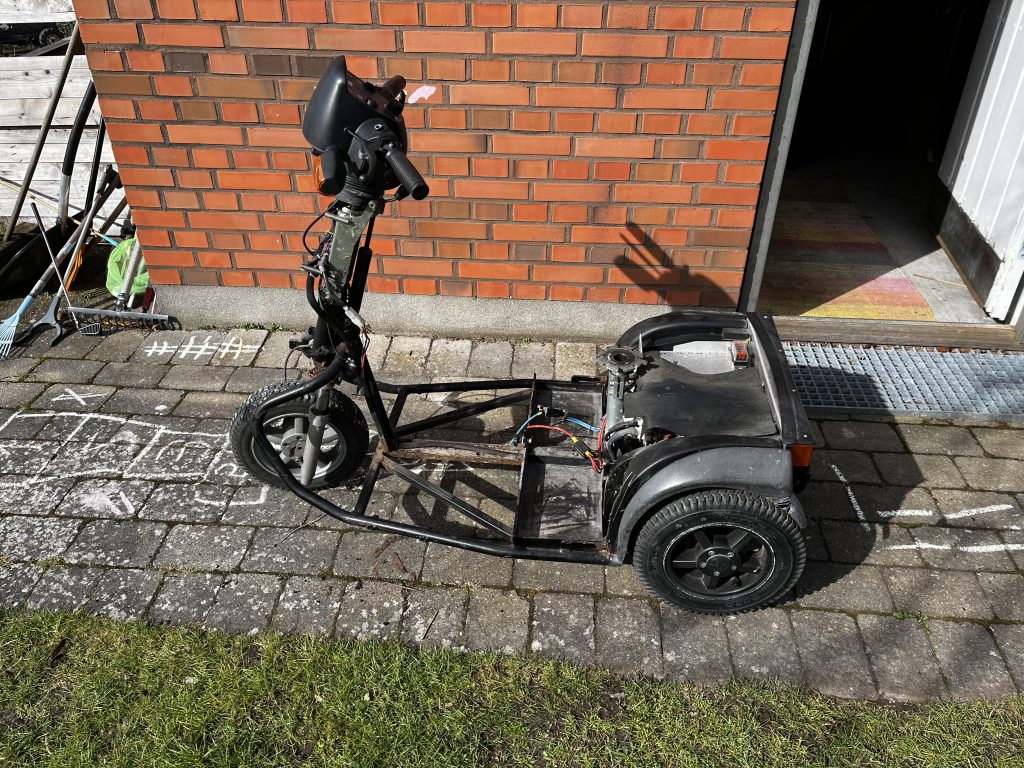
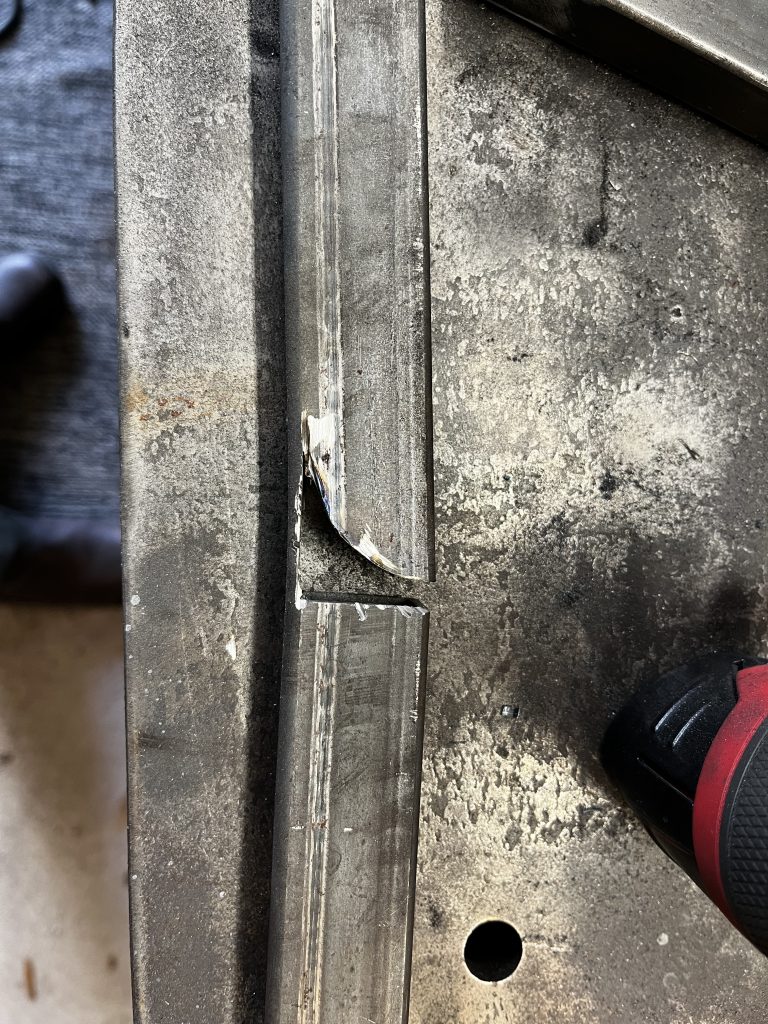
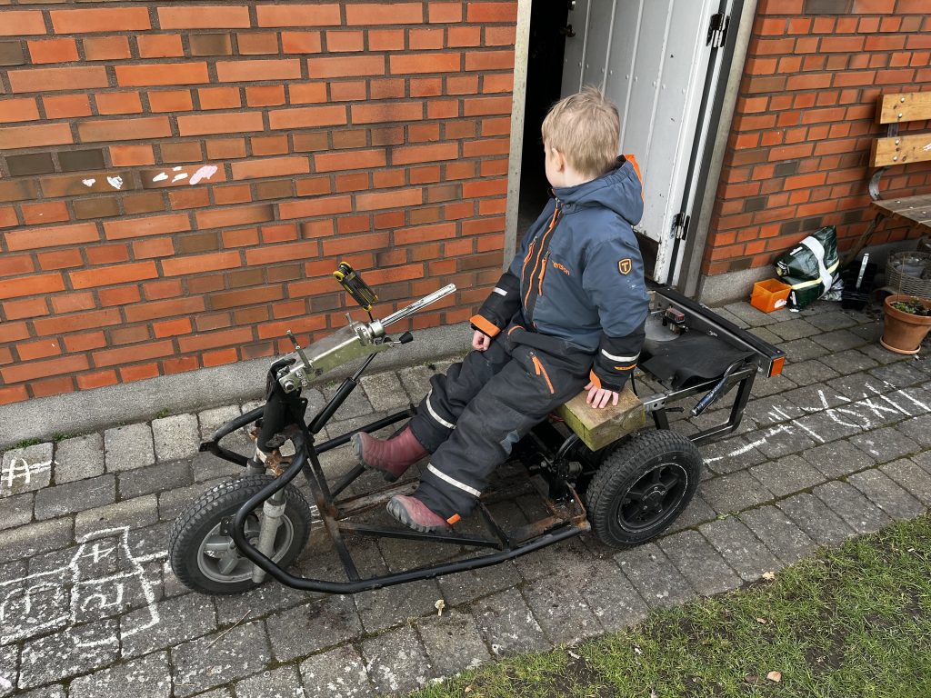
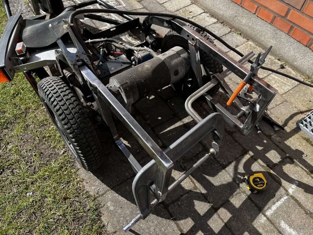
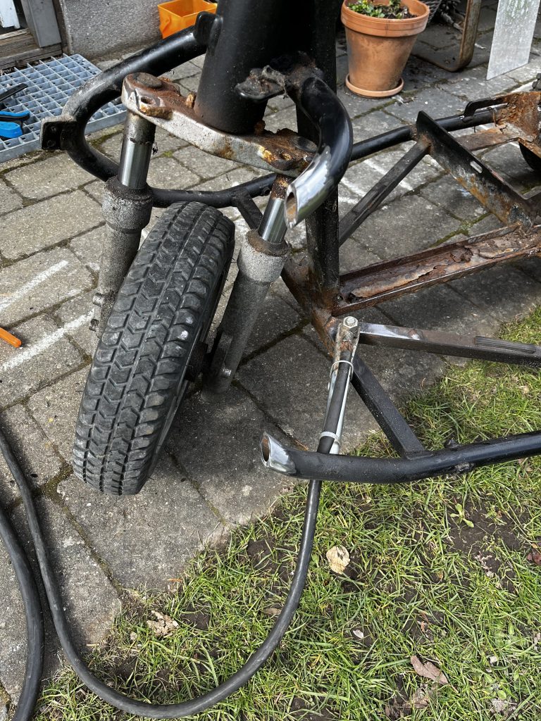
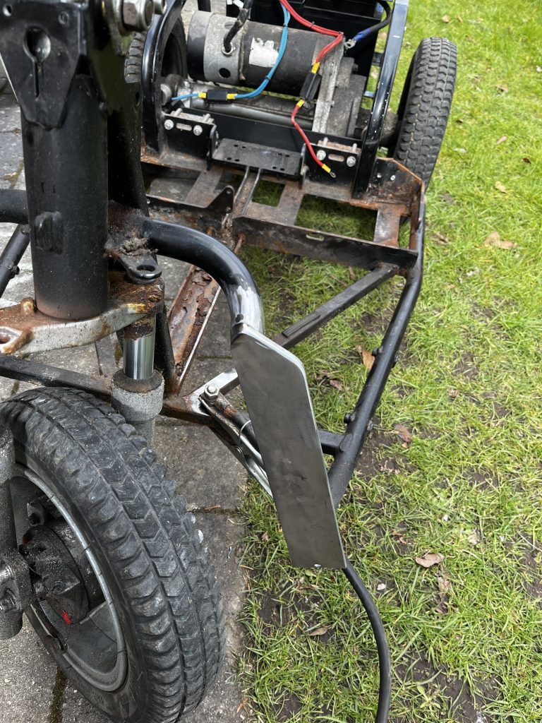
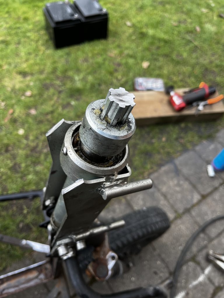
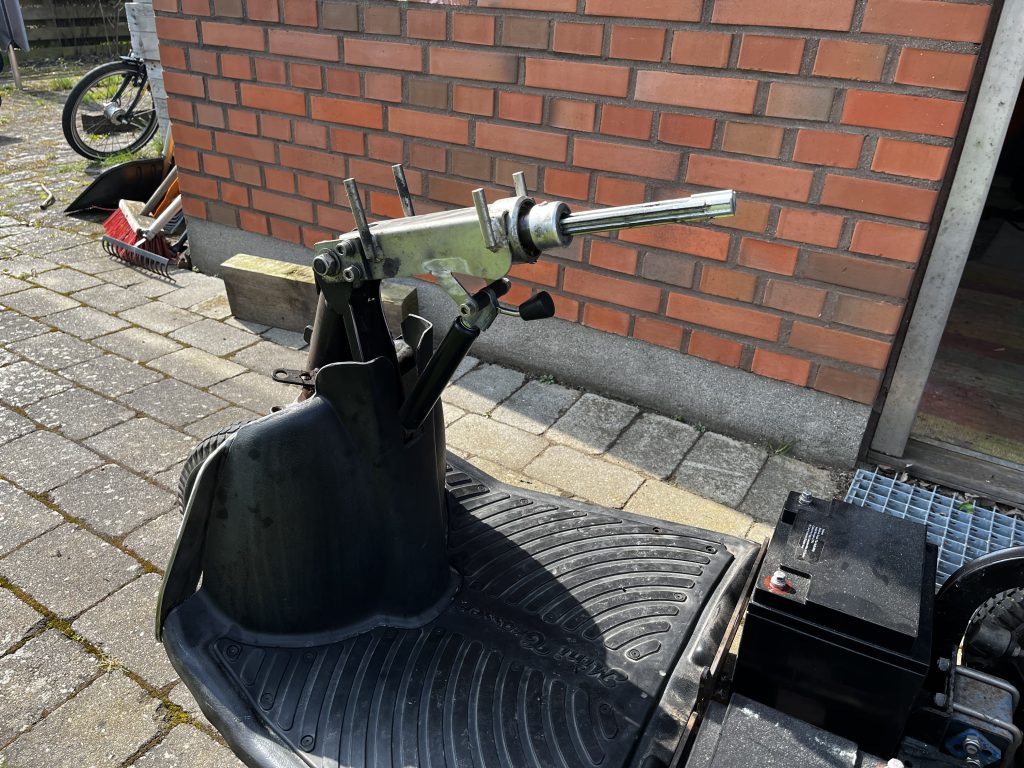
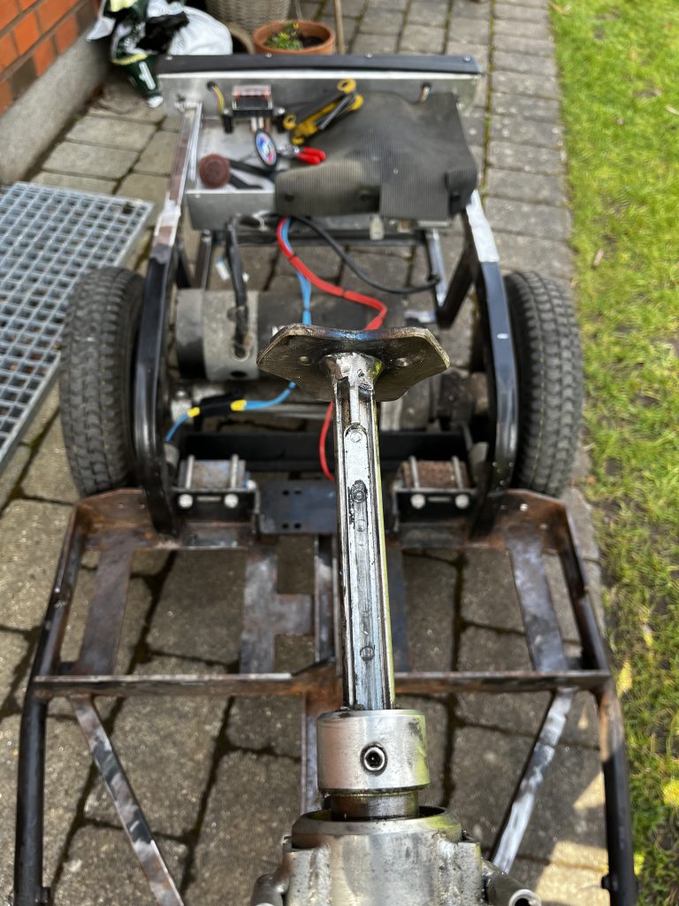
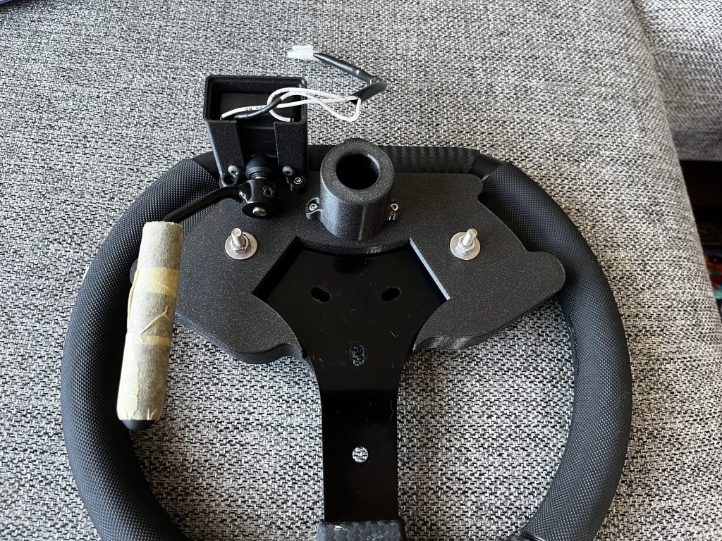
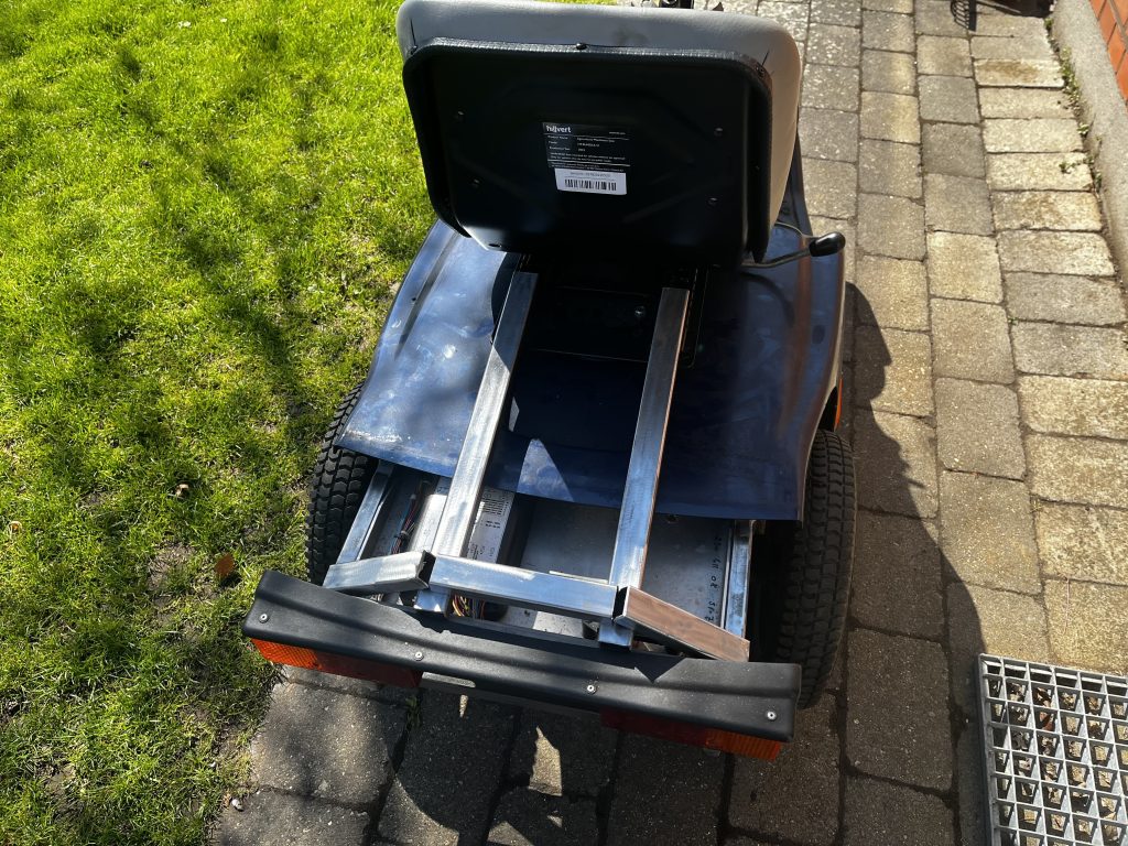
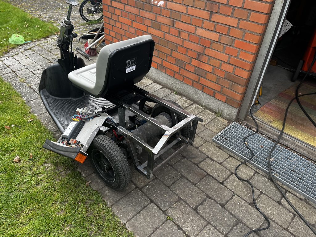
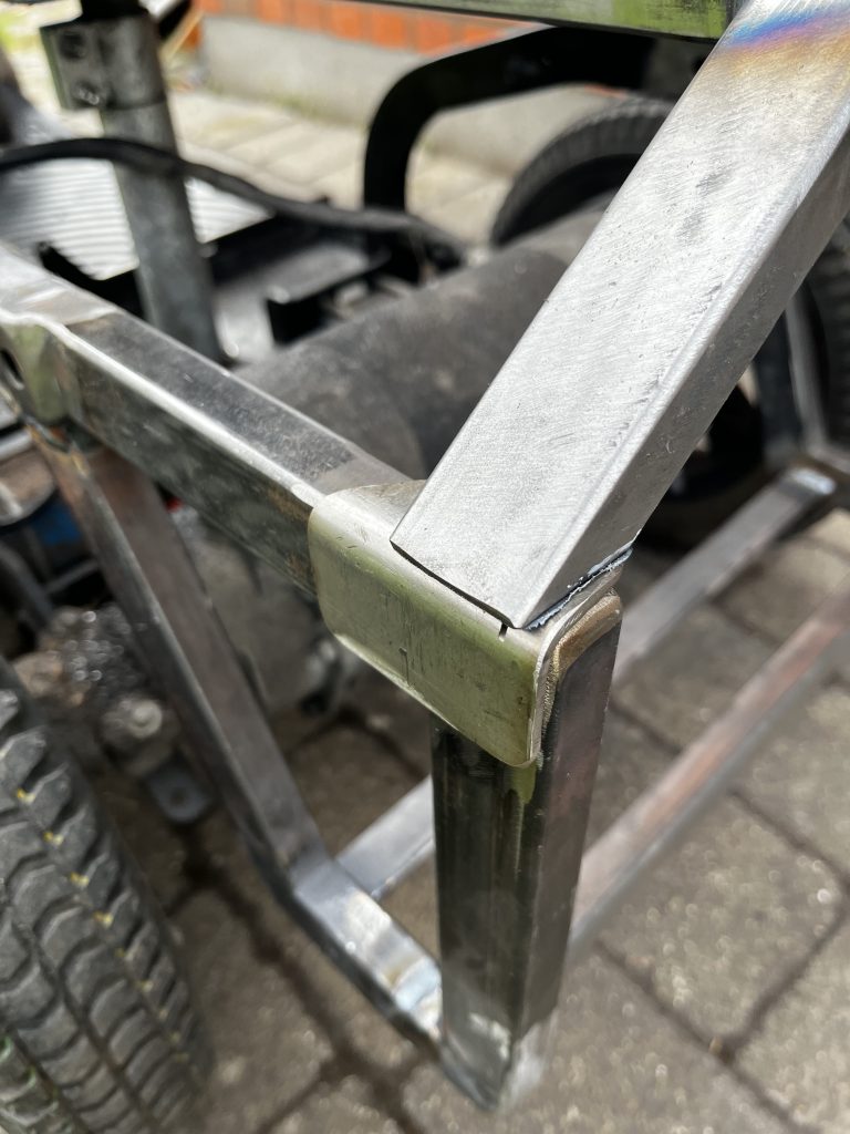
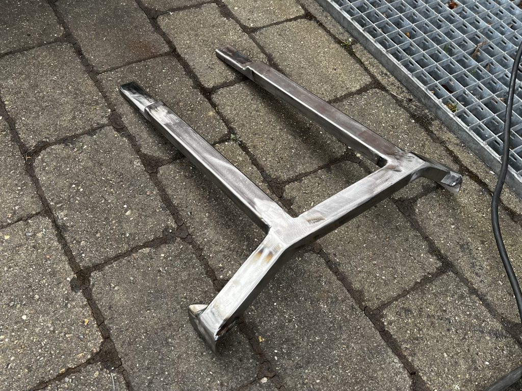
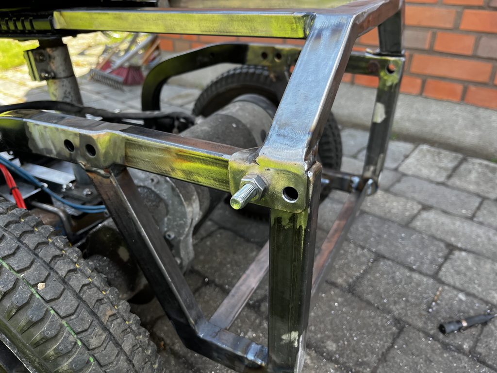
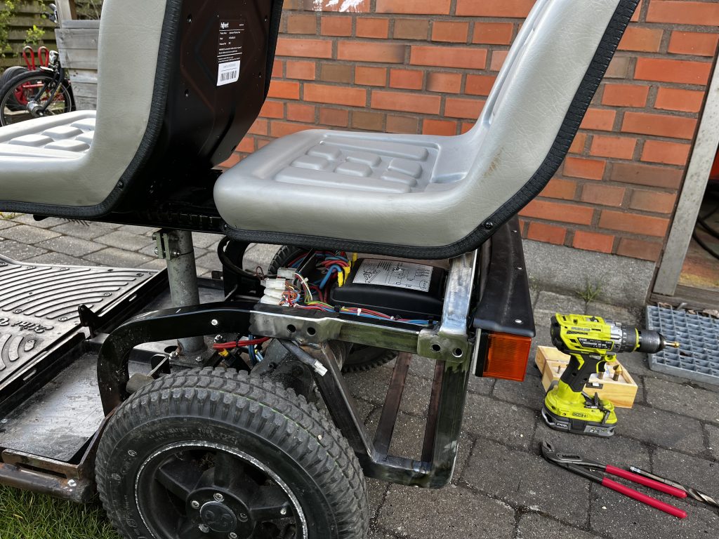
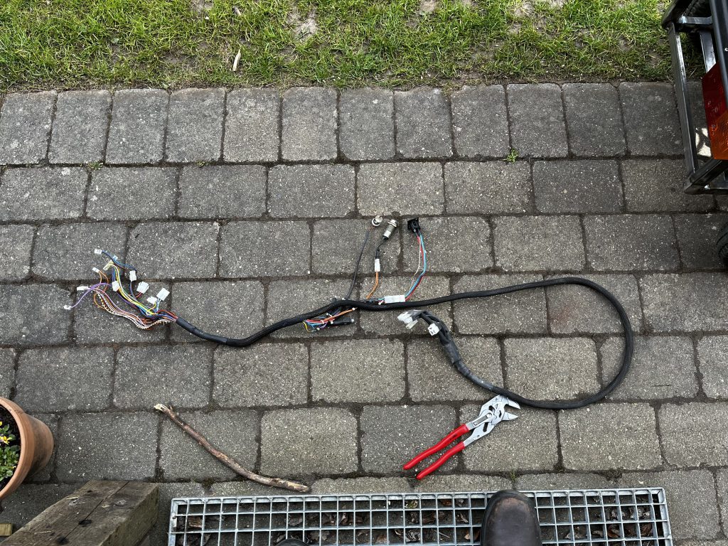
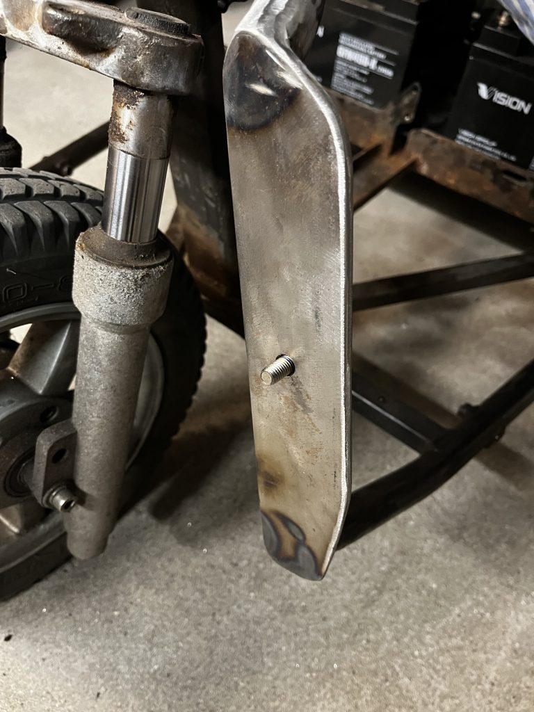
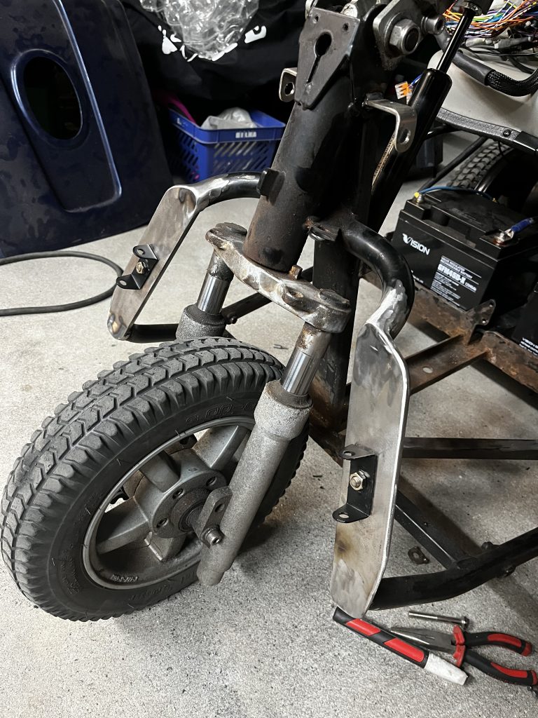
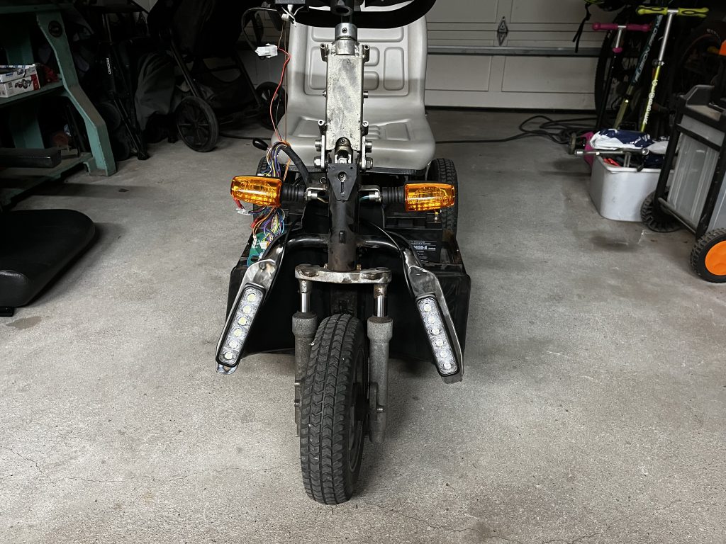
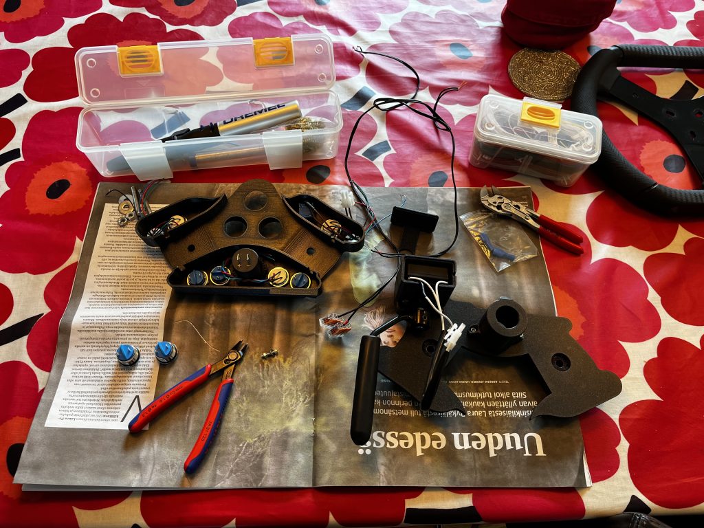
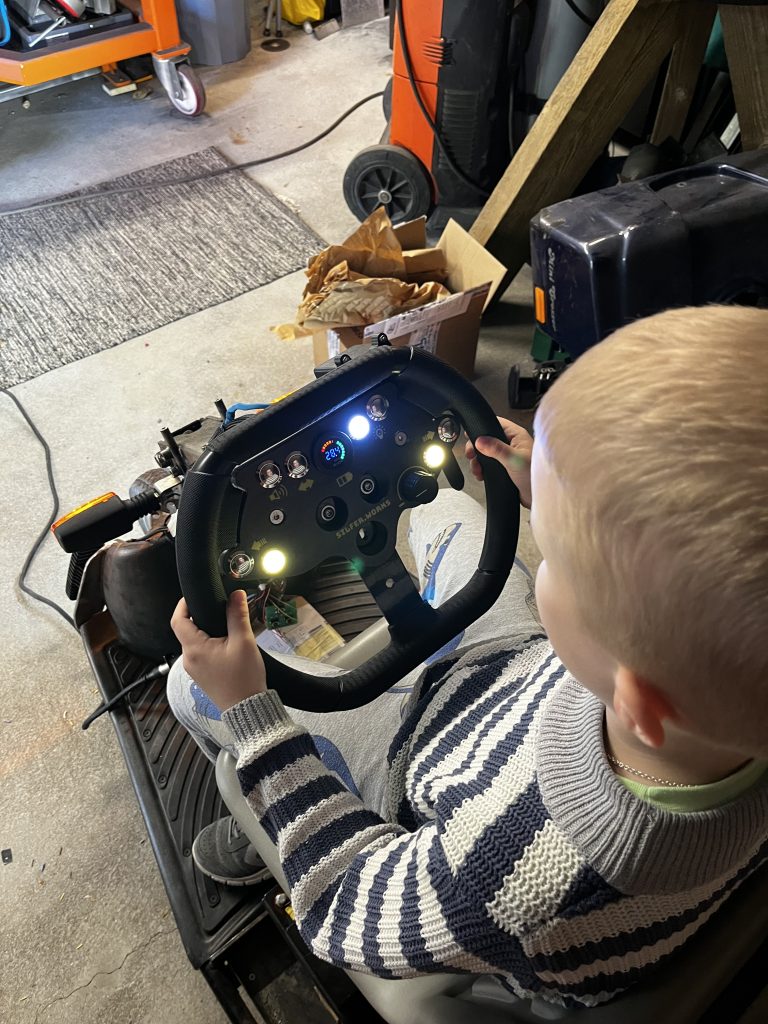
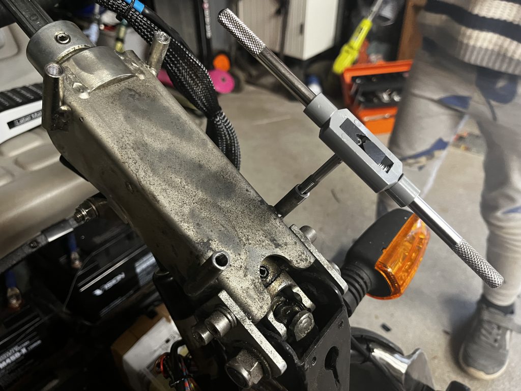
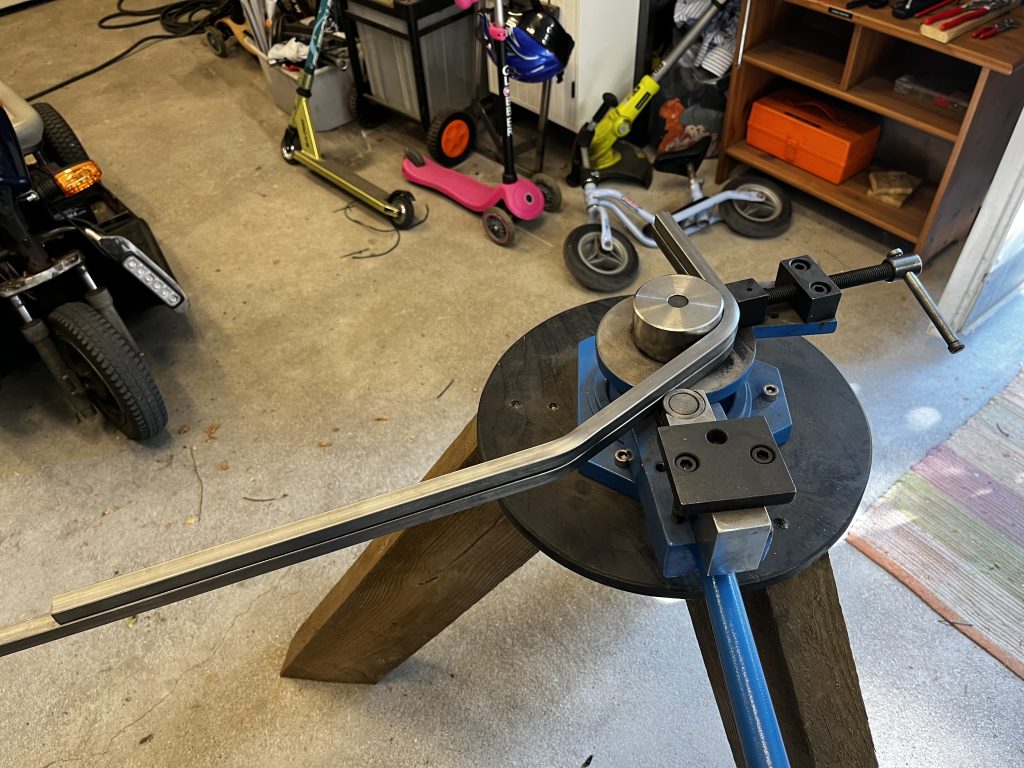
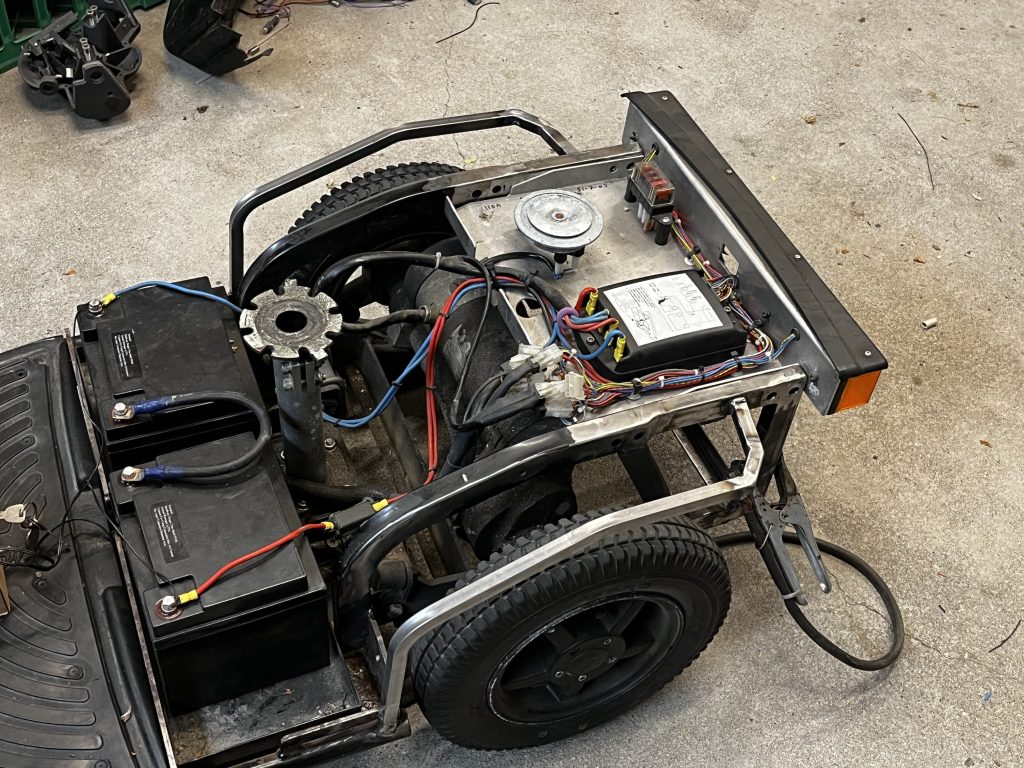
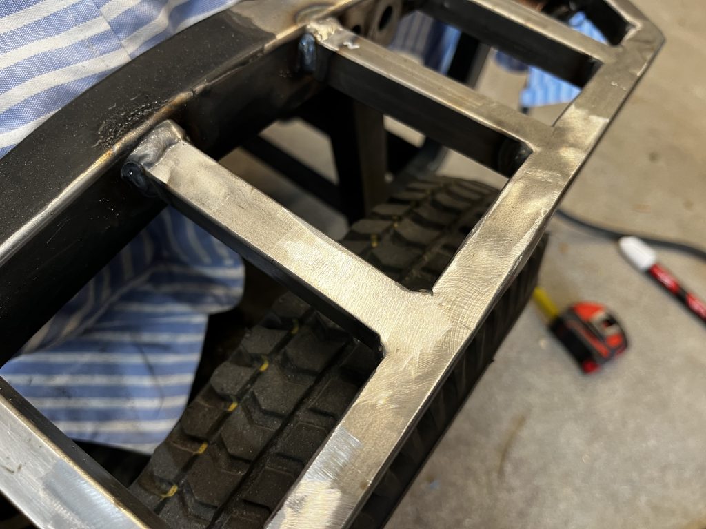
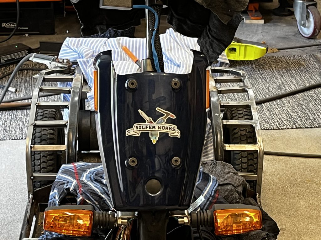
This was the only picture the ad had. I jumped into my car to have a look at it, and it was just perfect. But how do I get it home?I did the only reasonable thing: I drove it home! I of course did it on a Saturday night so there was loads of people on the local trains. This picture is from one of the live updates to my wife about how far I had gotten with my new mobility scooter. I sometimes wonder what she sees in me, it must be all the cool vehicles I drive…When I got it home, I found out that it was actually in a really good shape. The batteries could have been better but those are easy to replace if needed.Next day the disassembly started. The frame didn’t have too much rust either.I was going to do a total rebuild of the frame, but I changed my mind when I realised that it had hidden shock absorbers at the back. I will instead modify the existing frame.As I have two kids and I’d prefer not to hear constant complaining that the other one has driven the trike more, I will add two seats to it. To do this I will need to extend the frame.This is the guesstimate on how far it has to go. I will also need to move the whole motor/axle assembly further back to balance it out.I decided to add supports with rounded corners to the bottom.This will be a total overkill for the kids, but it needs to hold my weight as well!Rounded square pipe.First test for the location and height of the new driver’s seat.Squaring the frame. I would have needed some bigger clamps…It has a “special” look.I’m also getting rid of the extended supports on the front. It will be slightly shorter, and I can mount dual headlights here.Headlight location.The steering column needs to be modified as well. The plan is to add a go-kart steering wheel instead.One of the two new seats arrived. This is the smallest garden tractor seat I could find.The angle for the adjustable steering column had to be modified as well so it can be brought further down.Preparing for the steering wheel mount.The steering wheel will be mounted to it with M8 bolts.Yeah, it’s always interesting welding unknown metal. It seems to hold well but I somehow managed to screw up and not weld it straight. That will be fixed by the future me.More testing of the seat location, now with a steering wheel in place.The second seat arrived. It feels that I have extended the frame too far back. I don’t know where the passenger will put their feet either…At this point I modelled and printed an inlay for the steering wheel which will hold all the controls. You can see more details about there here: https://silfer.works/f1-style-go-kart-steering-wheel/Controls + adjustable speed controller.It has a hand throttle. Pull it towards yourself and the trike accelerates, push it away from you and it reverses. Perfect for kids.I finally concluded that it was a good idea to modify the front. Now both sides are done.I also decided to re-use the floor as I couldn’t think of what to replace it with. It was modified to fit with the new front-end.I also concluded that the frame was extended too far. That had to be chopped before I started to work on the mounts for the seats.This is how I imagine the subframe for the passenger seat will be. It will attach under the driver’s seat and will also be bolted to the frame at the back.I’m using the original rails for the front seat. The passenger seat’s subframe need to be thin enough to slide into the rail.Done.The other side was made thinner as well, and the rest of the shape welded together.This is how it slides to the original rails. The subframe has to be removable, so I’m using 3mm stainless plate which wraps around the frame. It will have holes which align with the aluminium tray holding the electronics under the passenger seat, and is bolted to the frame.It is removable as promised.And even the holes match.The passenger seat is bolted to the subframe from the bottom.It all lines up. I decided that the passenger will need to keep the feet on the side of the driver. I need to make it safe so there is no risk of getting your feet into the wheels…Perfect size for two small kids.Time to start thinking about the wiring harness and what attaches to it.Simple mount for the headlights. It’s welded from the back and ground smooth.The indicators are attached with a simple stainless bracket.Indicator and headlight brackets in place.Headlights and indicators in place. Wiring things up. I managed to ruin my expensive Knipex side cutters. On the positive side I concluded that the fuses works and my son learned how to change them.Wiring the F1 style steering wheel I made earlier.I hope I left enough space for all the wires…It works as expected. It even has emergency indicators which I believe will be very useful in the future…Final touches before the first test ride. The original front fairing is also re-used but it has to be mounted upside down and due to this the mounts had to be modified.It looks like it was made to be mounted like this. I even found nice black bolts from my mystery drawer.First test drive.The guard for the rear wheels has to be also made. I was considering everything from plexiglass to making it out from fibreglass. I opted to make a simple metal guard for now and maybe I have better ideas later on.Following the original shape of the frame.I didn’t want to strip the frame again, so I decided to just cover all of the electronics while welding.I will need to cover these holes with something if I keep this design in the future.It has a very industrial look.There is still a lot to do, but it drives perfectly. The batteries last for about 20km so we’ve been able to do trips to the local forest and just generally terrorise the neighbourhood.
You might wonder why it is called “Mesla”? My son asked if I’m building a Tesla for him. I answered that it’s almost the same as a Tesla but it’s a mess. 😉
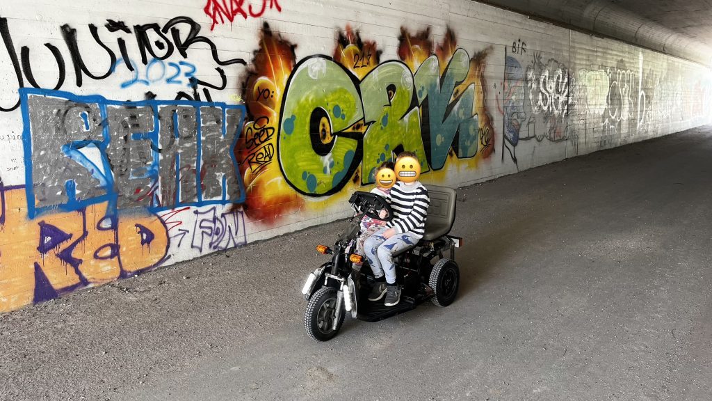
This is from one of the earliest test rides we had. The kids couldn’t agree who should come with as I was the one sitting at the back, so we decided to all go together. Me sitting at the back, and two kids on the front seat.